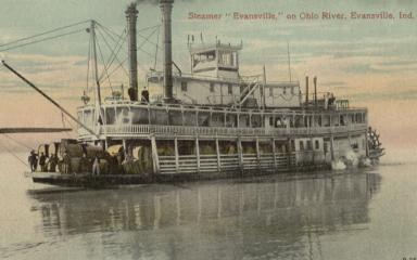
The "Evansville" was a Green River (Kentucky) sternwheel steamboat that ran from 1880 to 1931. For much of that time, she was running the Green River (Kentucky) trade. I was born in Evansville, Indiana, and brought up in a small river town near there, not far from where this boat ran. I've had quite an interest in building riverboat models since I was a kid. By my teen years, I was doing towboat and barge models out of posterboard. I built my first steamboat model when in my 20s, which was quite a while ago!
This is a quick overview of my current project - scratch building a 1/160 scale styrene model of the old gal. I hope you enjoy!
More photos here...
The "Evansville" was launched in Cincinnati in 1880, and operated under that name until 1897. She did most of her early work on the upper Ohio River, often running from Cincinnati to Wheeling (West Virginia), as well as on the Green River. By 1890, she was making trips to Cairo (Illinois), then back to the Green River trade.
She was rebuilt and renamed "Crescent City" in 1897, operating for the Louisville & Nashville Railroad. In 1906, she was again rebuilt, and given her original name, "Evansville".
On July 11, 1919, she sank at Aberdeen, Ky., but was quickly raised.
After many years of operating on the Green River, she pulled into the Bowling Green, Ky. wharf on July 25th, 1931. Supposedly, a carelessly-tossed cigarette started the fire that completely engulfed the old boat, and she was a total loss.
I build a lot of riverboat models. Being also into N scale model railroading, I usually build my boats in either HO or N scale. Since these are not kits, but are made from existing photos of real boats, I can resize the photos to use as a guide for modeling.
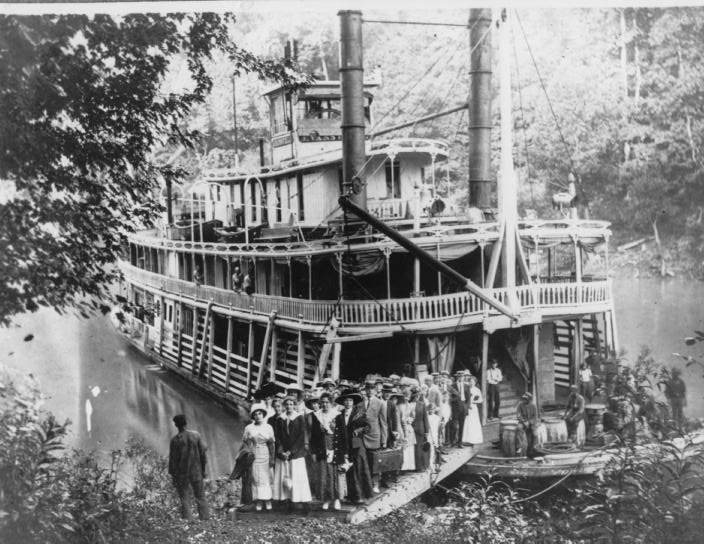
The first step was collecting the existing photos of the boat. All of the photos on this site are also elsewhere on the Internet, except possibly the 1920 view of her on the ways in Cairo.
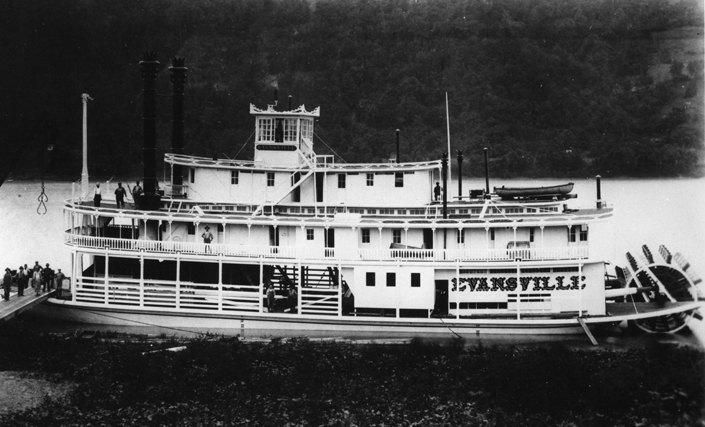
Having the wonderful Adobe Illustrator program on my computer, I was quickly able to enlarge the two port side views to 1/160. After tracing the features, I made one tracing in red, and the other in blue. I overlaid the two tracings, and combined them into one overall port side view, which was then resized (again) to the 1/160 length I had laid out. This was the basis for my hull and deck drawings. All drawings were modified, multiple times, to fit the available photos. (Even after cutting the boiler deck, I found that it was too narrow, so my drawings were modified and new plastic was cut.)
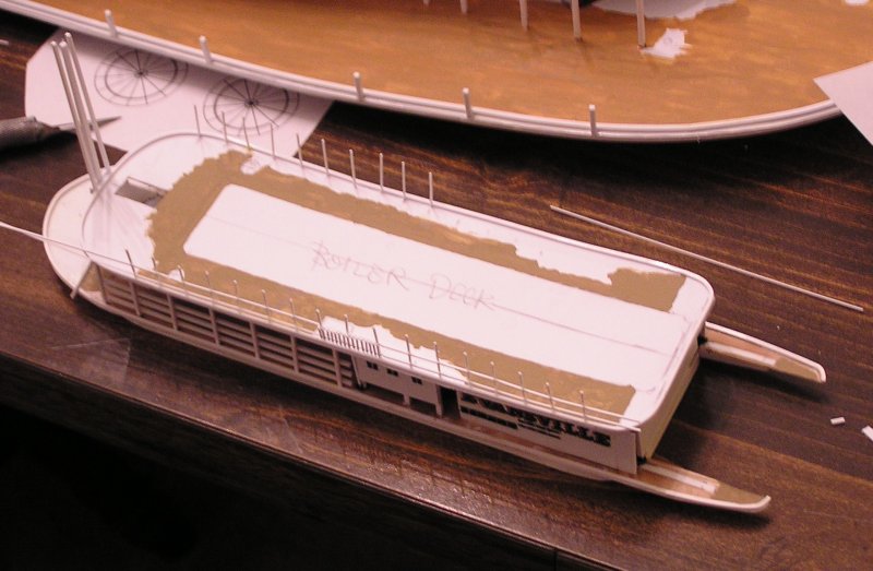
| With decent drawings in hand, I pulled a sheet of .030" styrene from my collection, laid out the larger pieces, and proceeded to cut. Although the Boiler Deck was cut, at this stage, it was too narrow. The Texas Deck remained in a template stage, at this point. Here is the result. | 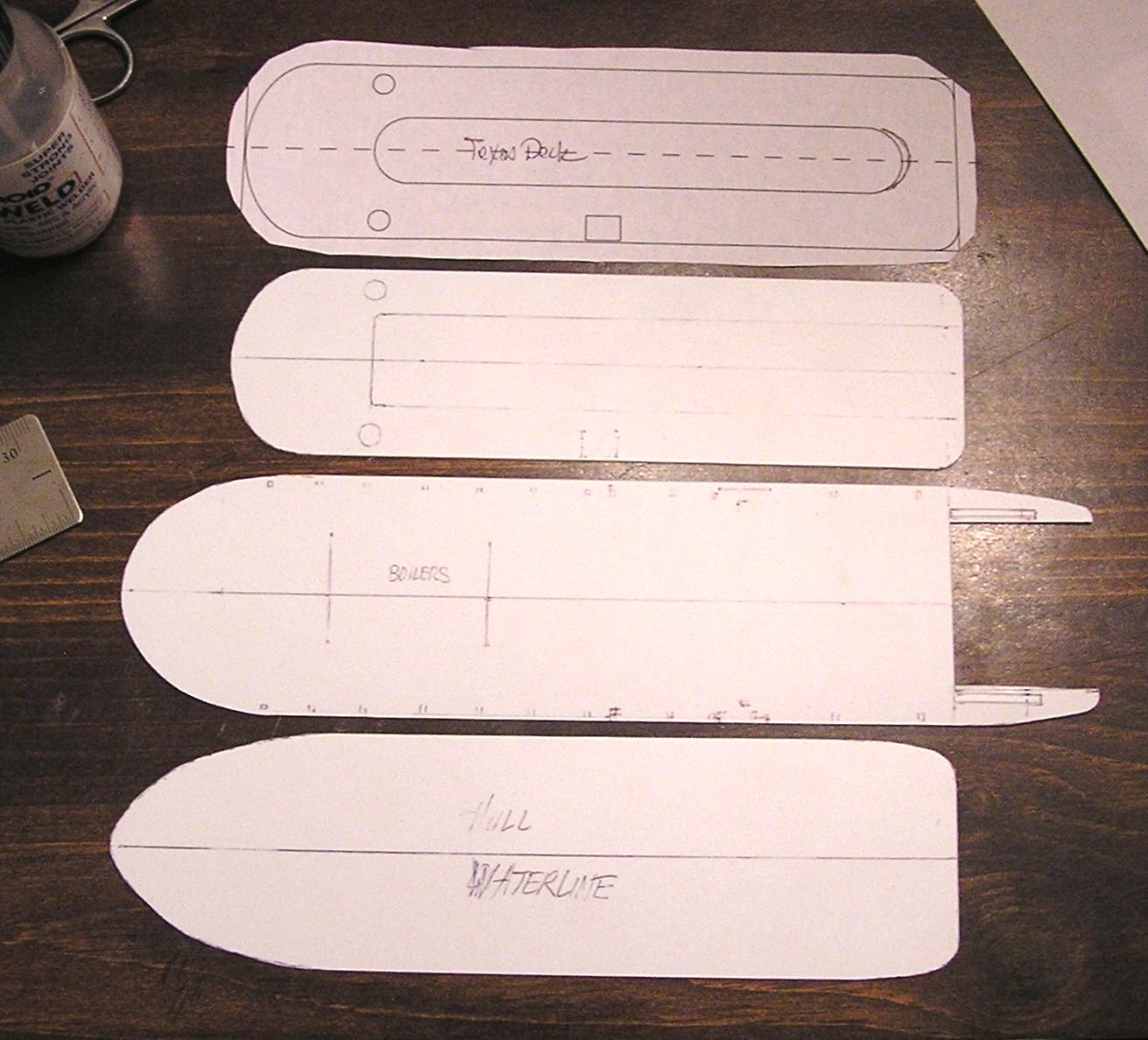 |
| Here is the waterline hull and Main Deck. The elevations for the top of the hull were taken from the combined port side photos. | 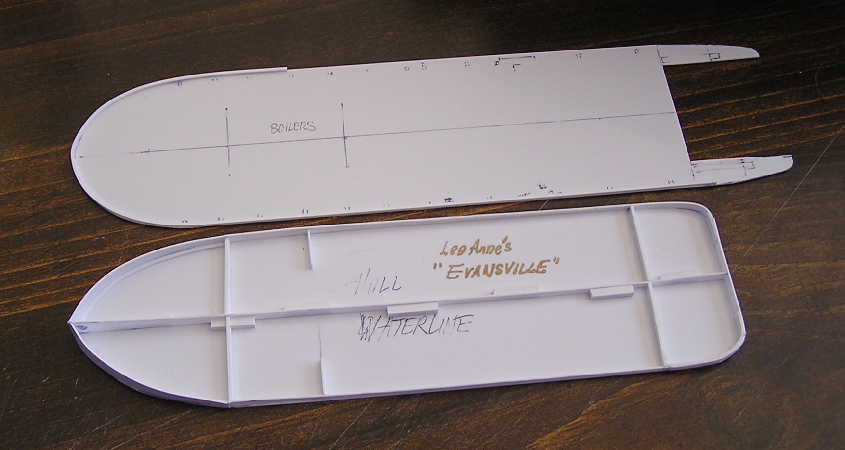 |
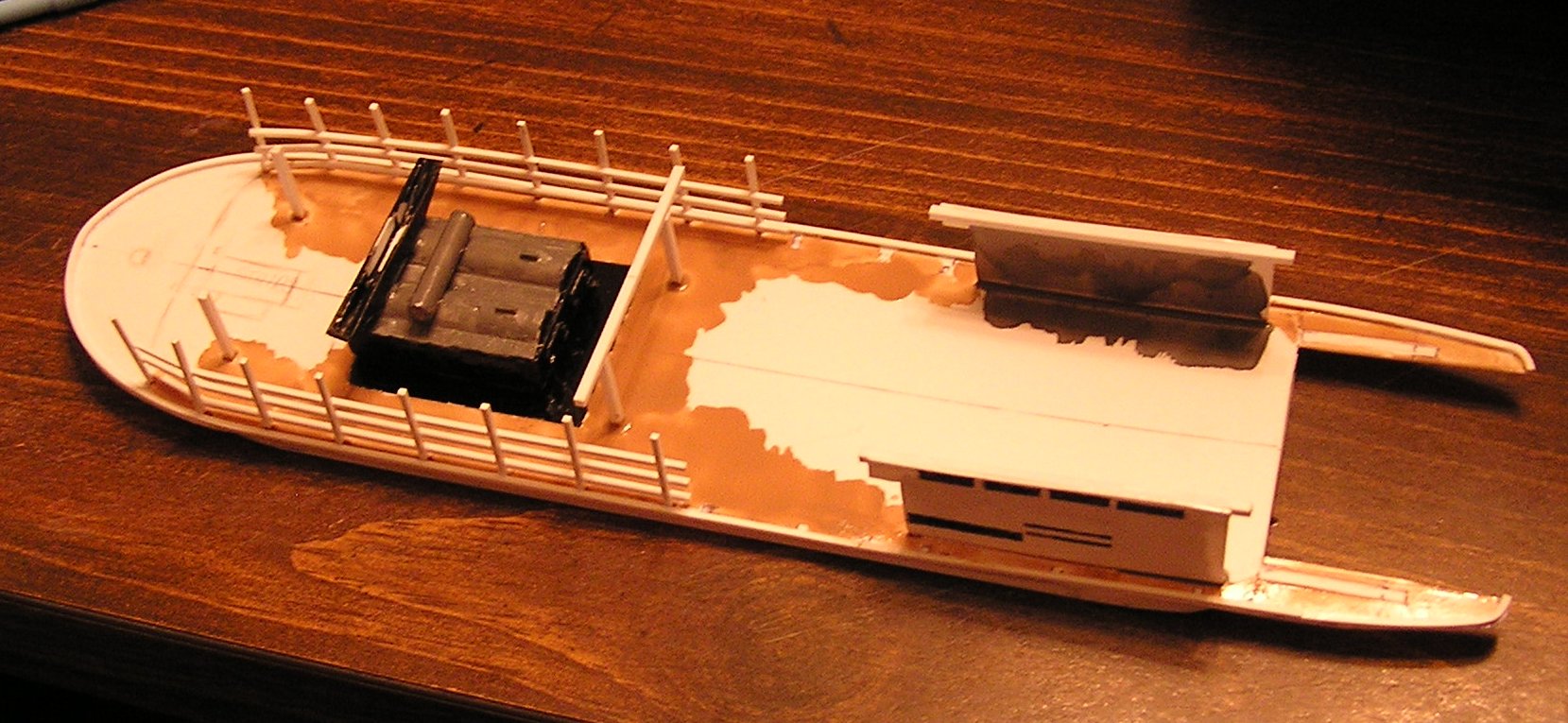
| Here, I've started laying out the Main Deck, including the location of the boilers, stairs, and capstan. The engine room side walls are in place. A lot of the placement came from a general knowledge of the layout of a sternwheel packet. I recommend Alan Bates' excellent book, The Western Rivers Steamboat Cyclopedium. | 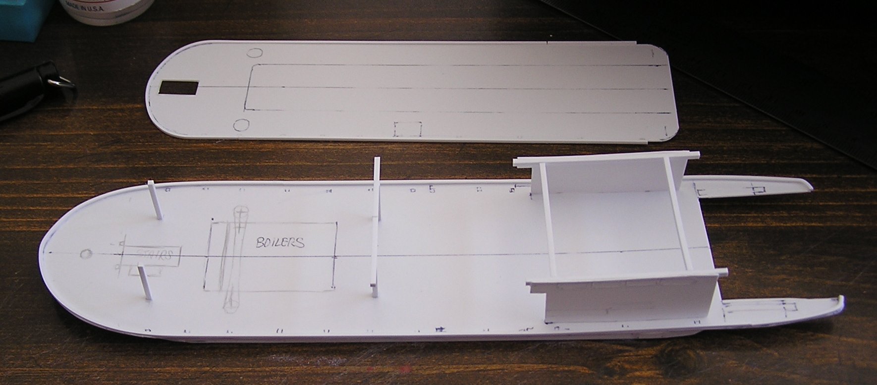 |
| This is a test fit of the Boiler Deck on top of the Main Deck. (No, the Boiler Deck was not the deck where the boilers were located!) The Boiler deck shown is the original one. A wider one was later cut. | 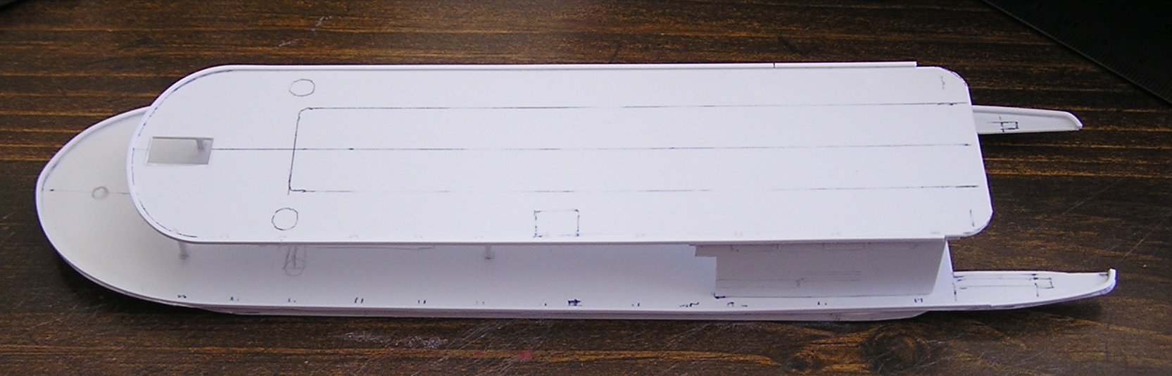 |
| Here is my build of the boiler assembly. The firebox is located underneath. The round structure going across the tops of the boilers is the steam drum. The structure on the far end is the flue, which will hook up to the bottoms of the two smoke stacks. The tops of the boilers were covered with a heat-resistant mixture. I believe it was mud and asbestos, but can't recall. | 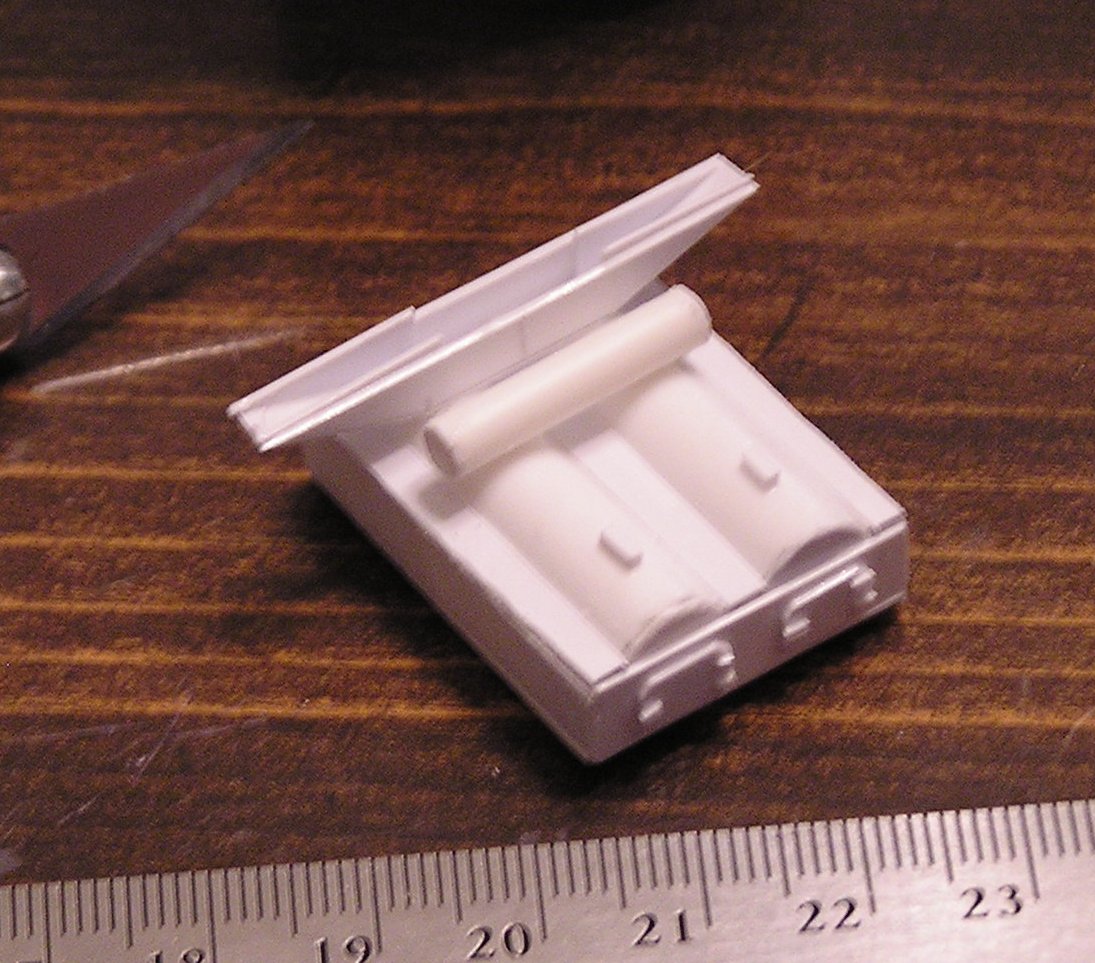 |
Here is the current state of the model...
Last modified Oct. 1, 2013